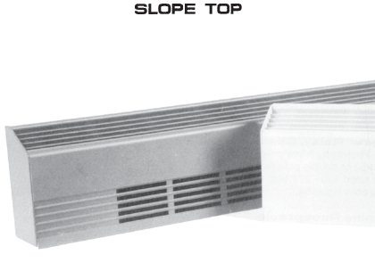
MODEL SBST/F
Model SBST/F Specifications:
- SBST Bottom intake, top discharge
- SBSTF front intake, top discharge
- 12 gauge extruded aluminum front and back
- Snap fit 2 piece construction
- SBST/F is 3″W x 6″H
- Enclosed junction boxes
- Full length thermal overload protection
- 1/4″ pencil proof discharge grill
- Aluminum fins for cool surface temperatures
- Standard 3/4″ EMT raceway
- Thermostat single or double pole, RT. or LF. Hand mounting
- Disconnect switch, double pole, RT. or LF. Hand mounting
- Painted and anodized finishes
- Pedestals available
- Control sections are 6″ or 12″: power relays, contactors, PE relays, trans former relays, duplex receptacle, fused disconnects and thermostat
- Accessories include: end caps, splice plates, wall trims, corners and blanks
- Length to 12′
- UL and CUL Listed

Suggested Engineering Specifications:
Design Draft Barriers shall be 6″ high and 3″ wide The front cover shall be one piece 12 gauge aluminum construction suitable for architectural, commercial and industrial use, with 1/4″ pencil proof slope top discharge.
The one piece cover shall be extruded aluminum for maximum strength and shall be available in lengths to 12′. The front cover shall snap fit to the 12 gauge back cover with no screw heads or assembly fasteners. The 12 gauge back cover shall be suitable for mullion to mullion mounting.
Standard painted finish shall be provided.
Heat sections from 2′ through 10′ shall be available. All heaters shall contain a 3/4″ EMT built-in raceway with factory wiring 1/2″ and 3/4″ knockouts shall be provided on the side and rear of the heater junction box to allow end to end wiring. All blank sections shall be fully enclosed to allow branch circuit wiring. All heaters shall contain a full length linear thermal overheat protector with automatic reset. Wattages shall be available from 100 to 250 WPF.
Heating elements shall consist of a steel sheath and mechanically bonded aluminum fins to assure efficient heat transfer. Element fin temperature shall not exceed 350 degrees Fahrenheit to ensure long element life. Element shall be center anchored and free floating at each end on nylon bushings.
Optional controls shall include:
Thermostats (single or double pole) and disconnect switches. Controls shall be tamper proof and adjustable with a blade screwdriver through the discharge grill.
Optional control sections include:
(See control features)
Accessories include:
(See accessories features)
All heaters are labeled by Underwriters’ Laboratories, Inc.
Operational Features
Model SBST/F features a tubular heating element with fins bonded to the sheath.
To prevent overheating in cases where the air discharge may be blocked, full length thermal overload protection is provided. The vacuum charged capillary automatically restores operation when the cause for overheating is removed. To ensure quiet operation, the heating element is anchored and free floating at each end on nylon bushings.
Installation Features
Model SBST/F construction allows simple, snap-fit installation. The back plate which houses the heating element assembly is simply attached to the wall surface at the desired height and the front cover enclosure is then snapped into place.
Pedestal Features
Model SBST/F-PD shall have 2″ adjustable pedestals and the heater back will be painted to match the front cover. 1″ of adjustment is available on the cast pedestal.
Pedestal Quantities
2 on 1′, 2′, 3′, 4′ and 5′, 6′
3 on 7′, 8′, 9′ and 10′
UL and CUL Listed
Note: Specify SBST or SBSTF
Accessories
Due to the size of the cabinet, controls other than thermostats and disconnects must be mounted in a control section. See below.
Control Sections:
12″ Control Sections:
12″ long and can be attached to the enclosure. Contains 1, 2, or 3 items. right or left side mounting. (6″ CS for 1 or 2 items).
Transformer Relay:
Single pole, rated 19 amp 120 – 277 volt. Contact rated up to 277 volt (specify). Coils are 24 to 277 volt (specify).
Power Relay, Contactors, PE Relays, Mercury Relay:
Single or double pole (specify). 25 amp rated 120 – 277 volt. Low or line volts coils (specify).
Duplex Receptacle:
Mounted on front cover. 15 amp rated 120 volt.
Fused Disconnect:
Fuse block with 20 amp fuse and disconnect switch.
Thermostats:
Single or double pole rated 22 amp 120 – 277 volt adjustable through discharge grill.
Disconnect Switch:
Double pole rated 20 amp 120 – 277 volt.
ACCESSORIES
- SB-WT Wall Trim (specify 2″ or 4″)
- SB-SP Splice Plate
- SB-EC End Cap (specify right or left)
- SB-IC Inside Corner (specify miter degree)
- SB-OC Outside Corner (specify miter degree)
- SB-BS Blank Section (specify length 6″ – 12′)
- SB Bottom Intake, Top Discharge\LBF Front Intake, Top Discharge
|
Length |
Nominal Watts/Ft. |
Heat Watts |
Cat No. |
Volts |
|
2′
|
150 200 250 |
300 400 500 |
2150 2200 2250 |
|
|
3′ |
100 150 200 250 |
300 450 600 750 |
3100 3150 3200 3250 |
|
|
4′ |
100 150 200 250 |
400 600 800 1000 |
4100 4150 4200 4250 |
|
|
5′ |
100 150 200 250 |
500 750 1000 1250 |
5100 5150 5200 5250 |
|
|
6′
|
100 150 200 250 |
600 900 1200 1500 |
6100 6150 6200 6250 |
|
|
7′ |
100 150 200 250 |
700 1050 1400 1750 |
7100 7150 7200 7250 |
|
|
8′ |
100 150 200 250 |
800 1200 1600 2000 |
8100 8150 8200 8250 |
|
|
9′ |
100 150 200 250 |
900 1350 1800 2250 |
9100 9150 9200 9250 |
|
|
10′ |
100 150 200 250 |
1000 1500 2000 2500 |
10100 10150 10200 10250 |
|
Other Wattages Available
120 Volt 100 or 250 W.P.F. only
