IMPORTANT! SAVE THESE INSTRUCTIONS
INSTALLATION AND OPERATING INSTRUCTIONS
Read All Instructions Before Using the Heater
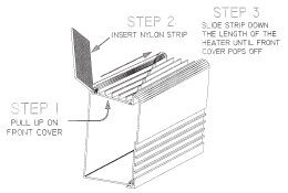
FRONT COVER REMOVAL
INSTALLATION:
Step 1: Heaters to be installed by a licensed electrician.
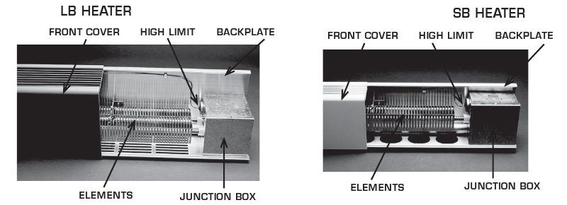
Step 2: Remove front cover by lifting top portion to unsnap from backplate (see above).
Step 3: Remove appropriate knockout on side or back of junction box.
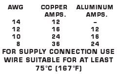
Step 4: Use suitable connector and wire in accordance with N.E.C. and local codes.
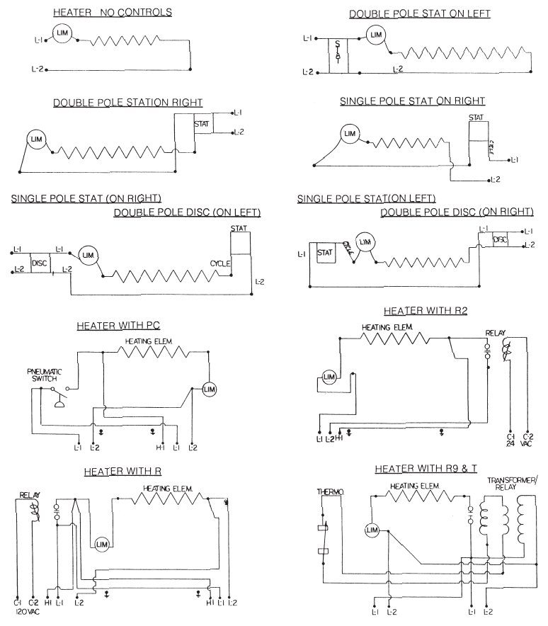
Step 5: Wire according to diagrams.
Step 6: Mount backplate to appropriate surface, using suitable fastener.
Step 7: Replace junction box cover. Secure with screw.
Step 8: Install accessories as needed. See page 4.
NOTE: Blanks may be used as a wire raceway if front is secured to backplate by means of screw(s). If front is not secured with screw(s), conduit or armored cable should be used in blank sections and corner sections.
GROUND CONTINUITY:
Continuity of ground must be maintained between junction boxes of heaters or blank sections in a continuous run. To ensure this, use either:
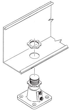
1. Listed conduit bushings or other chase nipples, having paint piercing type locknuts to join junction boxes.
2. Run a ground jumper from the ground screw in one junction box to the ground screw in adjoining junction box.
CAUTION: HIGH TEMPERATURE, KEEP ELECTRICAL CORDS, DRAPES AND OTHER FURNISHINGS AWAY FROM HEATER.
DO NOT INSTALL LESS THAN 1.5 INCHES ABOVE FLOOR ON BOTTOM AIR INTAKE STYLE
TOP![]()
DO NOT OPERATE HEATER WITHOUT FRONT COVER IN PLACE.
CAUTION HIGH TEMPERATURES:
Keep electrical cords away from heater. Do Not place heater below electrical receptacle. Do Not install heater against vinyl covered surfaces or foam surfaces. DO NOT install heater on paper or fabric covered surfaces.
Keep all draperies and furniture a minimum of 4″ from heater and 12″ above heater.
-WARNING-
High heat may discolor synthetic fabrics over time.
DO NOT install heaters against combustible, low density cellulose fiber surface.
DO NOT locate heater below an electrical receptacle.
DO NOT insert or allow foreign objects to enter any ventilation or exhaust opening as this may cause an electric shock, fire, or damage the heater.
To reduce the risk of fire, DO NOT store or use gasoline or other flammable vapors and liquids in the vicinity of the heaters.
IMPORTANT: HEATERS OVER 250 WATTS PER FOOT NOT FOR RESIDENTIAL USE
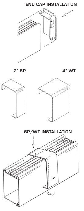
DRAFT BARRIERS AND PEDESTAL HEATERS
READ ALL OF THESE INSTRUCTIONS BEFORE USING THE HEATER
USERS GUIDE
–IMPORTANT INSTRUCTIONS–
SAVE THESE INSTRUCTIONS
–WARNINGS–
1. When using electrical appliances, basic precautions should always be followed to reduce the risk of fire, electric shock, and injury to persons, including the following:
2. Read all instructions before using this heater.
3. Heater has hot and arcing or sparking parts inside.
4. This heater is hot when in use. To avoid burns, do not let bare skin come in contact with hot surfaces. Keep combustible materials, such as furniture, pillows, bedding, paper, clothes and curtains away from heater.
5. To prevent possible fire, do not block air intake or exhaust in any manner.
6. Do not insert or allow foreign objects to enter any ventilation or exhaust opening, as it may cause electric shock, fire or damage the heater.
7. Read all information labels. Verify that the electrical supply wires are the same voltage as the heaters. All electrical work and materials must comply with the National Electric Code (NEC), the Occupational Safety And Health Act (OSHA) and all state and local codes.
8. CAUTION HIGH TEMPERATURES: Keep electrical cords away from heater. Do not place heater below electrical receptacle. Do not install heater against vinyl covered or foam surfaces. Do not install heater on paper or fabric covered surfaces. Keep all draperies and furniture a minimum of 4″ in Front of heater and 12″ above heater.
9. High heat may discolor synthetic fabrics over time.
10. DO NOT install heaters against combustible, low density cellulose fiber surface.
11. DO NOT install heater below an electrical receptacle.
12. DO NOT insert or allow foreign objects to enter any ventilation or exhaust opening, as it may cause an electric shock, fire or damage the heater.
13. To reduce the risk of fire, DO NOT store or use gasoline or other flammable vapors and liquids in the vicinity of the heaters.
14. WARNING!
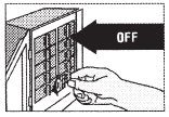 Turn the electrical power off at the electrical power board (circuit breaker or fuse box) and lock or tag the panel board door to prevent someone from restoring power while you are working on the heater. Failure to do so could result in serious electrical shock, burns, or possible death.
15. GROUND CONTINUITY: Continuity of ground must be maintained between junction boxes of heaters or blank sections in a continuous run. To ensure this either:
- Listed conduit bushing or other chase nipples, having piercing type locknuts to join junction boxes together.
- Run a ground jumper from ground screw in one junction box to ground screw in adjoining junction box.
WIRING DIAGRAMS
Wiring procedures and connections should be in accordance with the National Electric Code (NEC) and local codes.

 WARNING
When units are field drilled for mounting please take note:
1. Do Not drill next to the capillary tube. Allow 1/2″.
2. Do Not drill inside the electrical junction box.
3. Do Not drill next to the element. Allow 1/2″.
When units are not supplied with factory ko on the backplate, please take note:
1. Field installed ko’s can only be located as to NOT interfere with factory installed components.
2. Maintain 1/2″ spacing between live and dead metal parts.
MULTIPLE BASEBOARD WIRING -OPTIONAL-
Follow the instructions below if you are wiring more than one heater in parallel on the same circuit. If you are wiring multiple baseboard to one control, it is recommended to use one control per room.

OPERATING INSTRUCTIONS
The heater must be properly installed before it is used
1. If heaters have built in thermostats, adjust the shaft to the mid range and let run for a few hours. If the room temperature is too high, rotate the shaft counter-clockwise. If the room temperature is too low rotate the shaft clockwise until a comfortable temperature is achieved. Let the room temperature stabilize after each setting change.
2. The thermostat adjustment shaft and the disconnect switch are accessible through the grill opening at the left or right end of the heater.
3. The heater may emit a slight harmless odor when first turned on. This is caused by activating the internal heater components for the first time and should not occur again.
4. Select the setting for comfort on all thermostats if supplied.
MAINTENANCE INSTRUCTIONS
1. Before cleaning, make sure the power has been turned off at the circuit breaker panel.
2. Dust will collect between the element fins. The heater should be cleaned regularly for maximum efficiency.
Before cleaning the heater, be sure it is off and the element is cool. A vacuum cleaner with a brush attachment can be used for cleaning. The finish of the heater can be cleaned with a slightly damp rag.
3. Restore power to the heater.
4. All other servicing should be performed by a qualified, licensed electrician.
5. Furniture, Drapes and Carpet: Proper operation of heaters require free circulation of room air through the heating element. Keep electrical cords, drapes, rugs and other furnishings away from the heater. Furniture should be placed a minimum of 4″ from the heater. Drapes should clear the top of the heater by a minimum of 12″. If you prefer floor length drapes, they should be a minimum of 3″ above the floor and have a minimum clearance of 4″ from the back fold to the front cover of the heater.
6. For best results when carpeting is involved, allow the clearance of 1 1/2″ for carpet to be installed under the heaters and corners. Rugs can be placed up to the heater, provided that they are not of a thickness that would block the air in-take at the bottom of the heater.
7. If the front grill was removed for cleaning, replace the grill the same as it was before cleaning. If screws were used to hold the front cover or end caps, be sure to replace them.
LIMITED WARRANTY
Products covered by this warranty are warranted against defects in workmanship and materials for one year from date of sale. This warranty does not apply to damage from accident, misuse, or alteration; nor where the connected voltage is more than 5% above the nameplate voltage, nor to equipment improperly installed or wired or maintained to violation of the instruction sheet. This warranty is valid only in the fifty states of the United States. No other written or oral warranty applies. No employee, agent, dealer or other person is authorized to give any warranties on behalf of Design Architectural Heating. The customer shall be responsible for all costs incurred in the removal or re-installation and shipping of the product for repairs. Within the limitations of this Warranty, inoperative units should be returned to the nearest Design Architectural Heating factory, and we will repair or replace, at our option at no charge to you with return freight paid by Design Architectural Heating. It is agreed that such a repair or replacement is the exclusive remedy available from Design Architectural Heating and that Design Architectural Heating IS NOT RESPONSIBLE FOR DAMAGES OF ANY KIND, INCLUDING INCIDENTAL AND CONSEQUENTIAL DAMAGE. Some states do not allow the exclusive or limitation of incidental or consequential damages, so the above exclusion or limitation may not apply to you. This warranty gives you specific legal rights and you may also have other rights which vary from state to state. Merchandise returned to the factory must be accompanied by a return authorization and service identification tag. When requesting authorization, include all catalog numbers shown on the product.
DESIGN ARCHITECTURAL HEATING
P.O. Box 7110, Lewiston, Maine 04243

